WSN430 Open Node
The WSN430 open node is a WSN430 node based on a low power
MSP430-based platform, with a fully functional ISM radio
interface and a set of standard sensors. Concerning the
radio, two versions are developed: version 1.3b presents an
open 868 MHz radio interface while version 1.4 has an IEEE
802.15.4 radio interface at 2.4 GHz.
Specification WSN430 v1.3b & v1.4
| MCU |
16-bit Ultra-Low-Power, 48kB Flash, 10kB
RAMMSP430F1611
|
| sensors |
|
| radio communication |
- 860 MHz, highly configurable TI
CC1101
- 2.4 GHz, more high level TI
CC2420 (WSN430 v1.4)
|
| external memory |
1MB external flash memory ST M25P80 |
| LEDs |
green, red, blue |
| EEPROM serial number |
allowing unique identifier
DS2411
|
| power |
3,7V battery (830mAh) |
| Operating-System |
FreeRTOS, Contiki, Riot, TinyOS,
OpenWSN
|
| design |
WSN430 v 1.3

|
WSN430 v 1.4

|
More details on
GitHub
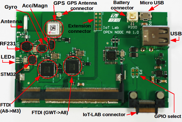
A8 Open Node
The A8 open node is the most powerful IoT-LAB node and allows
to run high-level OS like Linux. The main processor is a TI
SITARA AM3505 (Arm Cortex A8) combined with a STM32
micro-controller and a radio interface. It enables to run
applications used in advanced devices such as set-top box or
smartphone/tablet in order to concentrate sensors
information coming from a wireless sensor network.
Picture
Specification
| System on Module |
High-performance ARM Cortex-A8 microprocessor, 600
Mhz, 256 MB
Variscite
VAR-SOM-AM35 CPU |
| co-microcontroller |
| MCU |
ARM Cortex M3, 32-bits, 72 Mhz, 64kB
RAMST2M32F103REY
|
| sensors |
|
| radio communication
|
802.15.4 PHY standard, 2.4 Ghz AT86RF231
|
| LEDs |
green, red, blue |
| control |
USB device to control UART and
JTAGFTDI2232H
|
|
| power |
3,7V LiPo battery, 650 mAhGMB 063040 |
| option |
GPS deviceMAXQ
|
| links |
Ethernet, USB |
| operating-system |
Linux |
| design |
|
More details on
GitHub
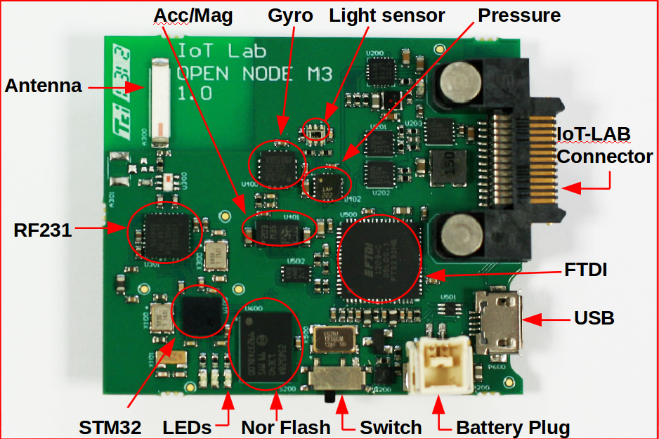
M3 Open Node
The M3 open node is based on a STM32 (ARM Cortex M3)
micro-controller. Like the WSN node this next generation
contains a set of sensors and a radio interface. Main
evolutions are a more powerfull 32-bits processing, a new
ATMEL radio interface in 2.4 Hz and more sensors.
Picture
Specification
| MCU |
ARM Cortex M3, 32-bits, 72 Mhz, 64kB RAMST2M32F103REY
|
| sensors |
|
| radio communication |
802.15.4 PHY standard, 2.4 GhzAT86RF231
|
| external memory |
128 Mbits external Nor flashN25Q128A13E1240F |
| LEDs |
green, red, blue |
| power |
3,7V LiPo battery, 650 mAhGMB
063040 |
| Operating-Systems |
FreeRTOS, Contiki, Riot |
More details on
GitHub
DES Node
Wireless Mesh Routers
The mesh
routers are based on the PC Engines Alix2c2/Alix2d2
and Alix3d2
embedded PC boards with the following features:
| CPU
|
500 MHz AMD Geode LX800 |
| DRAM |
256 MB DDR DRAM |
| Ethernet |
2 Ports |
| WIFI |
3 IEEE 802.11a/b/g |
| Expansion |
2 Mini PCI slots
2 USB 2.0 ports |
| Storage |
CompactFlash socket |
| Eclosure |
Custom |
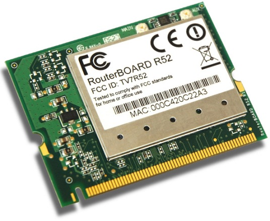
Each router is equipped with three IEEE 802.11a/b/g network
interface cards (NICs). Currently, we use one LogiLink WL0025
dongle based on the RT2501U architecture with an RT2571W BB/MAC
IC and RT2528 RF IC. This NIC features an on-board R-SMA
connector and a 4 dBi Hi-Gain antenna. The antennas are mounted
at the side panels of the router using extension cables.
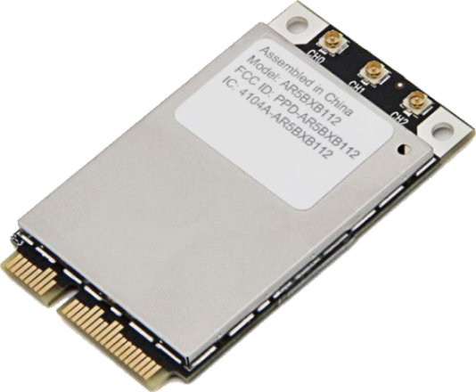
Additionally, all mesh routers are equipped with two
Atheros-based MiniPCI cards (WLM54SAG) connected with dual-band
antennasThe indoor nodes use a custom case that is
manufactured at Freie Universität
Berlin.
Wireless Sensor Nodes
Each mesh router is equipped with a MSB-A2
sensor node (developed at Freie Universität Berlin)
that is connected via a USB cable which provides power supply
and is used to write firmware images to the flash memory.
The MSB-A2 sensor nodes use an LPC2387
microcontroller produced by NXP Semiconductors. The frequency of
the 32-bit ARM7 TDMI-S core based microcontroller can be
dynamically configured at runtime to up to 72 MHz, depending on
the sensor network application and energy requirements. The TI
(formerly Chipcon) CC1100
transceiver uses the ISM band at 863 to 870 MHz with a maximum
data rate of 500
kbit/s. The MSB-A2 nodes set up a wireless testbed in parallel
to the mesh
routers that is fully orthogonal to the frequency band used by
IEEE 802.11.
| Microcontroller
|
NXP Semiconductors
LPC2387 |
| CPU Frequency |
up to 72 MHz |
| RAM |
98 KiB |
| Flash |
512 KiB |
| Transceiver |
Chipcon CC 1100 |
| Expansion |
GPIO pins
mini USB 2.0 port |
| Storage |
microSD-card socket |
The sensor nodes are equipped with a Sensirion SHT-11 temperature
and humidity sensor. Depending on the experiment scenario,
extensions are connected on-demand via the general purpose
input/output pins (GPIO) or the second on-board mini USB port.
In addition to the internal 512 KiB flash memory, microSD-cards
can be used. Unlimited data storage is available via the
Ethernet backbone provided by the mesh routers.
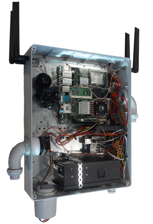
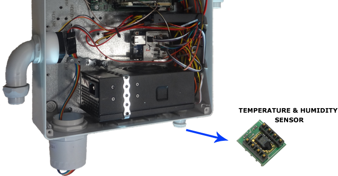
NITOS Outdoor Nodes
The upgraded Outdoor Nodes have been developed by the NITLab
team and support MIMO operation. The new version of the
Outdoor Nodes are equipped with 802.11a/b/g and
802.11a/b/g/n wireless interfaces. They also feature 2-core
Intel cpus, new generation solid state drives and usb web
cameras. Last but not least, each node is equipped with
light, temperature and humidity sensors.
Specification
| Motherboard |
Features two Gigabit network interfaces and supports
two wireless interfaces
|
| CPU |
CPU Intel Core 2 Duo P8400 2,26 GHz |
| RAM |
2G DDR3 |
| Wireless Interfaces |
Atheros 802.11a/b/g & Atheros 802.11a/b/g/n (MIMO)
|
| Chassis Manager card |
NITlab CM card |
| Storage |
SSD Drive |
| Power Supply |
350 Watt mini-ATX |
| Antennas |
Multi-band 5dbi , operates both on 2.4Ghz & 5Ghz
|
| Pigtails |
High quality pigtails (UFL to RP-SMA) |
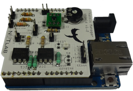
NITlab CM card
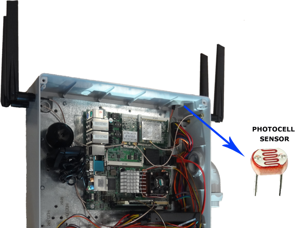
In order to control and monitor Outdoor nodes' operation, we
use NITlab's Chassis Manager Card (CM card). A tiny web
server is running on the CM card and serves http requests,
such as power on/off and reset commands. Further more, CM
card can support real time sensor measurements, since it can
be connected with temperature & humidity sensors, as well as
with light sensors.
Picture
Two leds are used to indicate the operational status of the
outdoor nodes. More specifically a two state led, located on
the side, indicates the power status of the node. If the led
is red the node is turned off and if the led is blue the
node is turned on. The same led flashes in red mode each
time the cm card serves a request.
The second led is on the cm card and indicates the
connection of the node to the power supply.
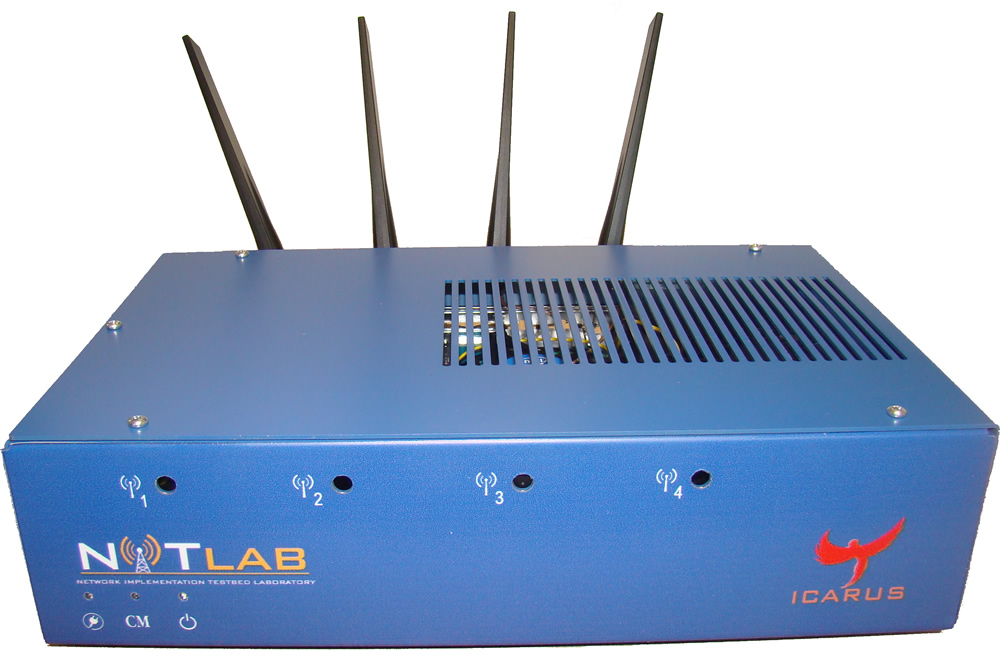
Icarus Nodes
NITlab has developed powerful Wi-Fi nodes, called ICARUS, in
order to support the increasing demand of state-of-the-art
resources for experimentation in NITOS facility.
Experimenters are able to run and evaluate demanding
processing algorithms and protocols in a large scale
testbed. Icarus nodes are equipped with 802.11a/b/g and
802.11a/b/g/n wireless interfaces and feature new generation
intel 4-core cpu's and new generation solid state
drives.
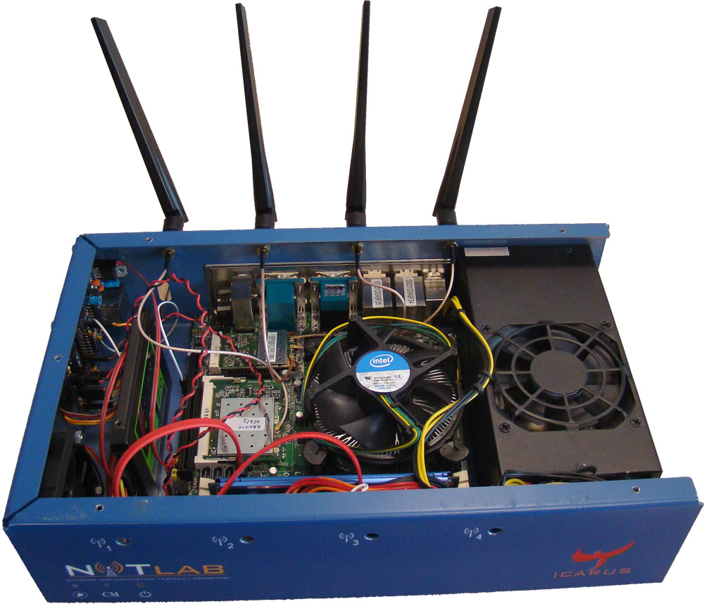
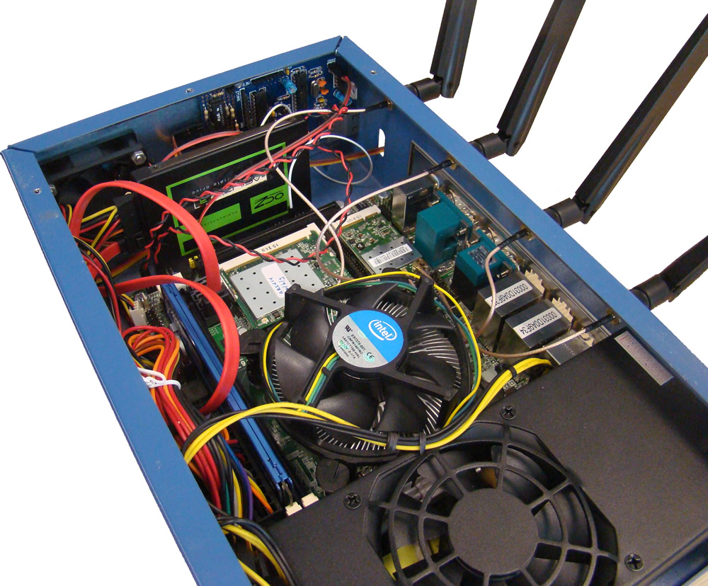
Specification
| Motherboard |
Features two Gigabit network interfaces and supports
two wireless interfaces
|
| CPU |
Intel® Core™ i7-2600 Processor, 8M Cache, at 3.40
GHz
|
| RAM |
8G DDR3 |
| Wireless Interfaces |
Atheros 802.11a/b/g & Atheros 802.11a/b/g/n (MIMO)
|
| Chassis Manager card |
NITlab CM card |
| Storage |
SSD Drive |
| Power Supply |
350 Watt mini-ATX |
| Antennas |
Multi-band 5dbi , operates both on 2.4Ghz & 5Ghz
|
| Pigtails |
High quality pigtails (UFL to RP-SMA) |
NITlab CM card
In order to control and monitor Outdoor nodes' operation, we
use NITlab's Chassis Manager Card (CM card). A tiny web
server is running on the CM card and serves http requests,
such as power on/off and reset commands. Further more, CM
card can support real time sensor measurements, since it can
be connected with temperature & humidity sensors, as well as
with light sensors.
Picture
Two leds are used to indicate the operational status of the
outdoor nodes. More specifically a two state led, located on
the side, indicates the power status of the node. If the led
is red the node is turned off and if the led is blue the
node is turned on. The same led flashes in red mode each
time the cm card serves a request.
The second led is on the cm card and indicates the
connection of the node to the power supply.
SAM R21 open node
The SAMR21 open node is based on an Atmel SAM R21 Xplained
Pro evaluation kit built on top of an Atmel ARM Cortex M0
micro-controller. This new open node also contains an IEEE
802.15.4 Atmel radio interface at 2.4 GHz.
The SAMR21 Open Node can reset, debug and program the ARM
Cortex M0 through the embedded debugger (EDBG) connected to
the gateway USB port. This component also allows a UART
connection to the M0. The input power source is configured
through the power management.
IoT-LAB special configuration
The serial connection baudrate should be configured at 115200
bauds in the firmware.
Schematics and Datasheets
In details, the main hardware components contained in the
node are :
-
ATSAMR21G18A
(48 MHz, 32bits, 32kB RAM, 256kB flash)
- Radio interface 2.4 GHz AT86RF233
- One on-board LED (orange)
Extensions with sensors
Some nodes in Saclay site (custom-1 to custom-5) are equipped with Atmel I/01 Xplained extension. On those nodes, extra sensors are also available:
To use this node: www.iot-lab.info
source:
github.com/iot-lab
m400 nodes
Onelab deployed a chassis of ARM64 servers in its facility at Sorbonne University in Paris.
The chassis is a 4.3U HP Moonshot and carries 45 servers blades, with two network switches.
m400 Node Specification
| CPU |
Eight 64-bit ARMv8 (Atlas/A57) cores at 2.4 GHz (APM X-GENE)
|
| RAM |
64GB ECC Memory (8x 8 GB DDR3-1600 SO-DIMMs)
|
| Disk |
120 GB of flash (SATA3 / M.2, Micron M500)
|
| NIC |
Dual-port Mellanox ConnectX-3 10 GB NIC (PCIe v3.0, 8 lanes) |
To use this node: Cloudlab platforms tutorials