Inria Grenoble – Rhône-Alpes
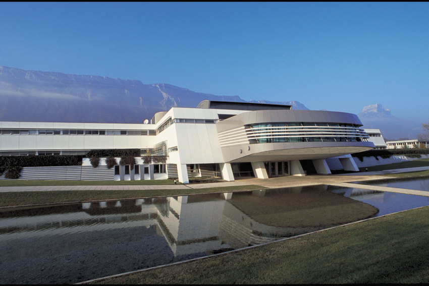
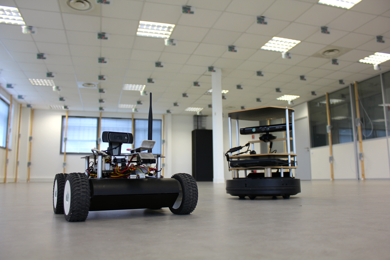
Grenoble testbed is located at Inria Grenoble – Rhone-Alpes in Montbonnot.

Access to Computer Networking Testbeds
A wide variety of world class testbeds available through your one account
Grenoble testbed is located at Inria Grenoble – Rhone-Alpes in Montbonnot.
Detailed testbed documentation one can find on GitHub Pages
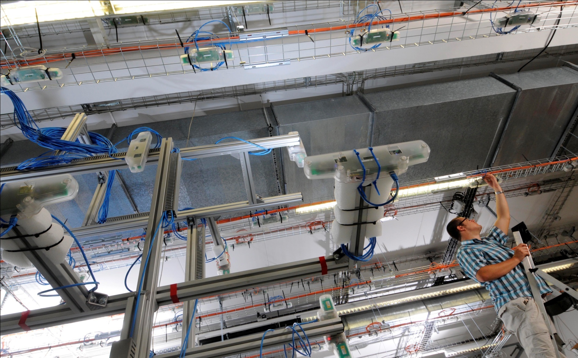
Picture by Christophe Finot
| M3 open nodes | 320 |
| fixed | 256 |
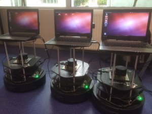
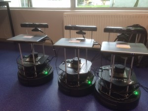
| mobile on robots (mix of Wifibot and Tutlebot 2) | 64 |
| open host nodes | 64 |
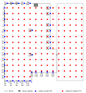
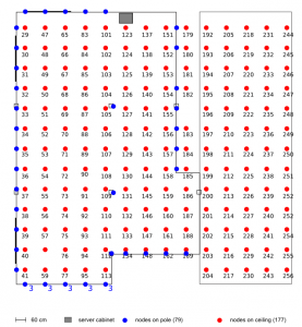
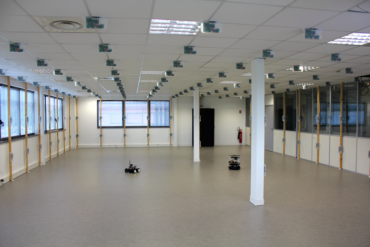
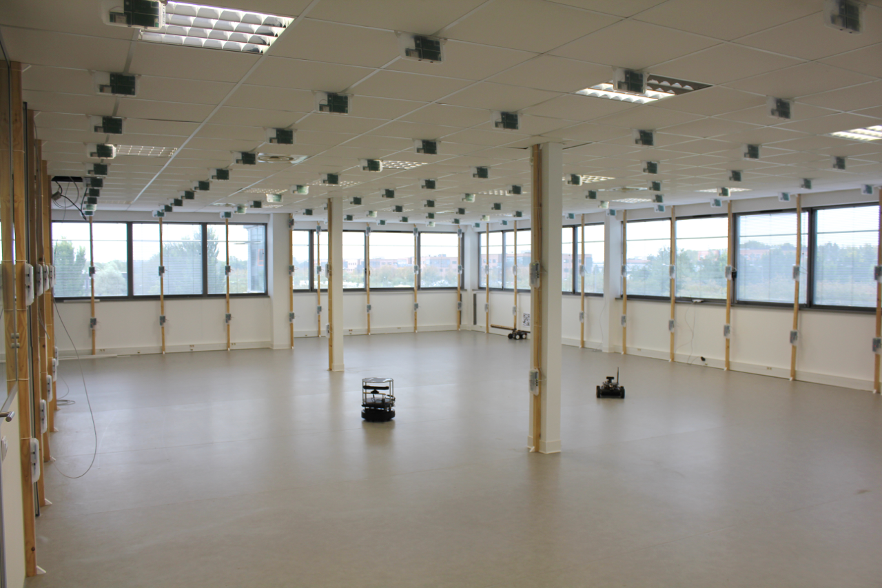
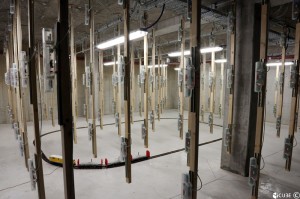
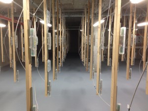
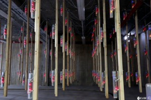
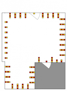
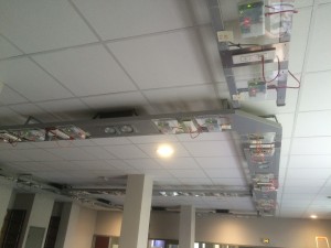
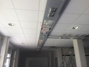
Lille testbed is deployed over a 225 m2 area, composed of a corridor separating a big room and 5 offices (respectively on left and right in topology figures). Nodes are dispatched over the ceiling and wood poles, situated at the borders of the big room.
Detailed testbed documentation one can find on GitHub Pages
Strasbourg testbed is located at ICube laboratory.
| WSN430 open nodes | 256 (10 mobile nodes on robots) |
| M3 open nodes | 120 (25 mobile nodes on robots) |
| A8 nodes | 24 (8 mobile nodes on robots) |
Detailed testbed documentation one can find on GitHub Pages
The Saclay testbed is located at Saclay – Île-de-France
The platform is distributed over the basement of a digiteo 2 building, a room in digiteo 1 and another room in digiteo 2.
The basement is isolated from the other rooms: node can’t see each other.
| A8 nodes, equiped with GPS | 175 |
| M3 nodes, all located in the Digiteo 2 room | 12 |
| Atmel SAM R21 Xplained Pro nodes, distributed over digiteo 1 and 2 rooms | 8 |
| WSN430 nodes | 120 |
Detailed testbed documentation one can find on GitHub Pages
You can follow your experiment live on the A8 node with identifier 145 here
Rennes Testbed is located at INRIA Rennes.
| WSN430 open nodes | 256 |
Detailed testbed documentation one can find on GitHub Pages
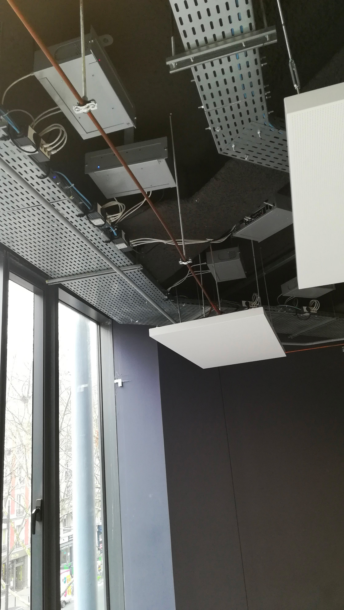
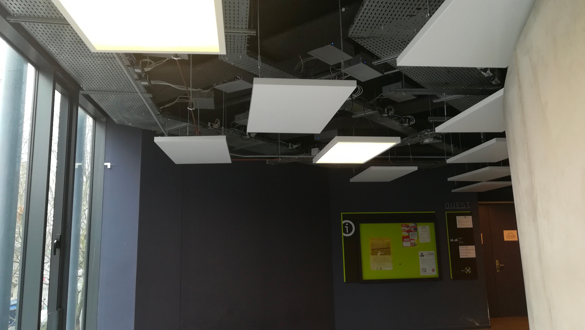
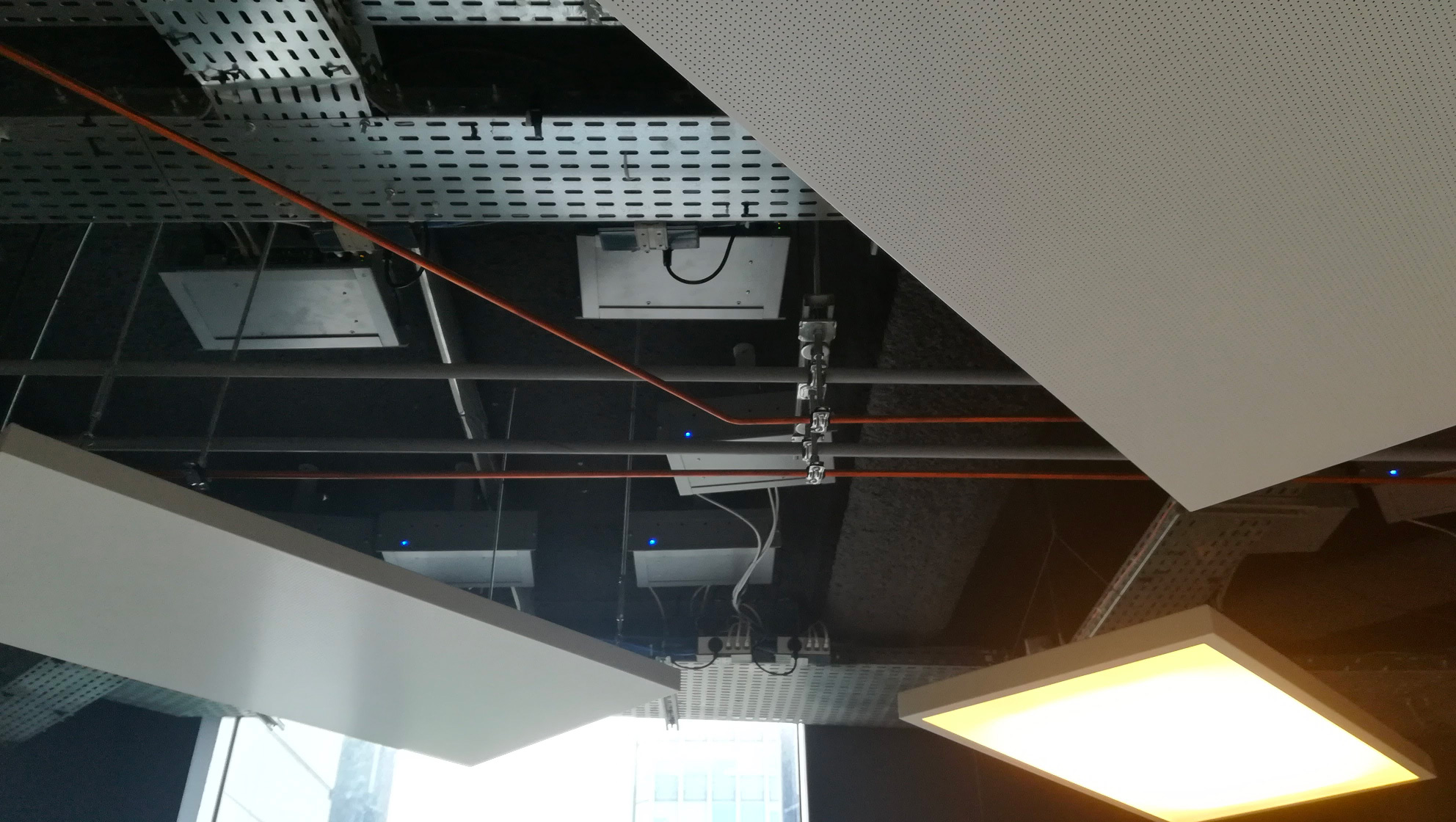
Paris testbed is located at Institut Mines-Telecom, Paris XIII.
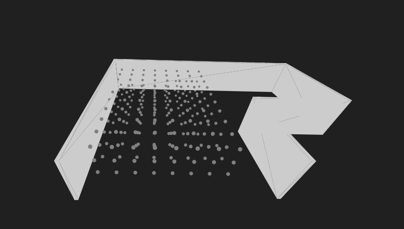
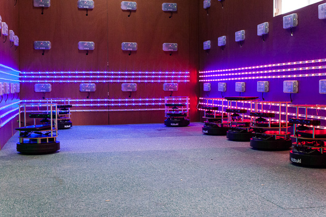
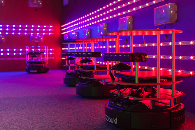
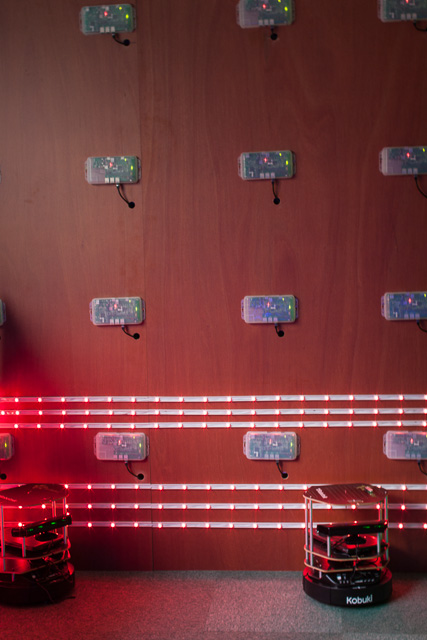
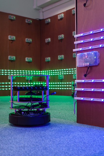
The Paris testbed is composed of 160 nodes pinned on the walls of a 35 m2 L-shaped room on 4 horizontal rows.
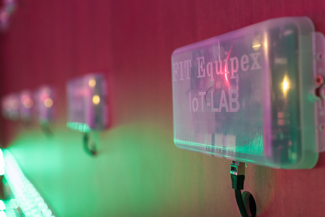
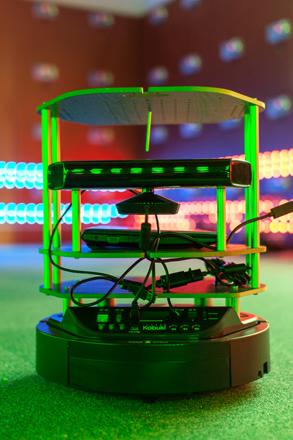
In the middle, 10 robots (Turtlebots) will soon move and be able to adapt thieir behavior to what they see through their camera. To influence robots mobility, the room is surrounded by 6 RGB LED strips (each strip contains about 280 LEDs) that are fully configurable by the experimenter. The color of each LED can be defined independently, allowig the user to simulate a moving target or physical phenomena to which the robots can respond.
Detailed testbed documentation one can find on GitHub Pages
This testbed is located in an experimentation room which belongs to the CITI laboratory and the Telecommunications Department of INSA Lyon, Villeurbanne. The target uses of this room are quite different: practical works with students, robots/drones testing, wireless sensor networks experimentation, Wi-Fi security evaluation, services deployment, etc. During your experimentation, this room could be shared with others practical works. Basically, we claim that this room is useful to observe the behavior of nodes with this dense interactivity.
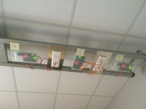
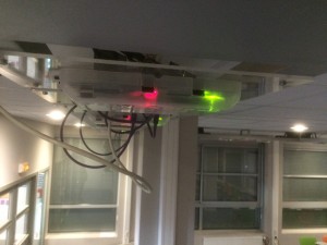
Lyon testbed is deployed over a 80 m2 area, composed of a single room. Nodes are dispatched over the ceiling, situated along several lines.
Nodes on ceiling are dispatched along 5 lines at 2.78 m high.
The floor of the big room will be dedicated to a fleet of robots.
Detailed testbed documentation one can find on GitHub Pages
Berlin testbed is located at Freie Univerität Berlin.
| DES nodes | 50 |
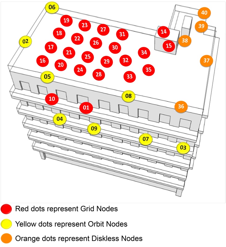
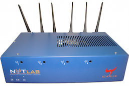
NITOS Outdoor deployment consists of powerful nodes that feature multiple wireless interfaces and allow for experimentation with heterogeneous (Wi-Fi, WiMAX) wireless technologies.
The NITOS wireless nodes, in all the aforementioned deployments, are equipped with two wireless cards, one 3x3 MIMO 802.11 a/b/g/n card and an 802.11 a/b/g card, which can both work in Station, Ad-Hoc, Mesh Point and Access Point Mode in both bands, 2.4 GHz and 5 GHz.
| GRID nodes | 24 |
| Orbit nodes | 8 |
| Diskless nodes | 5 |
Nodes are deployed at the exterior of a University of Thessaly (UTH) campus building.
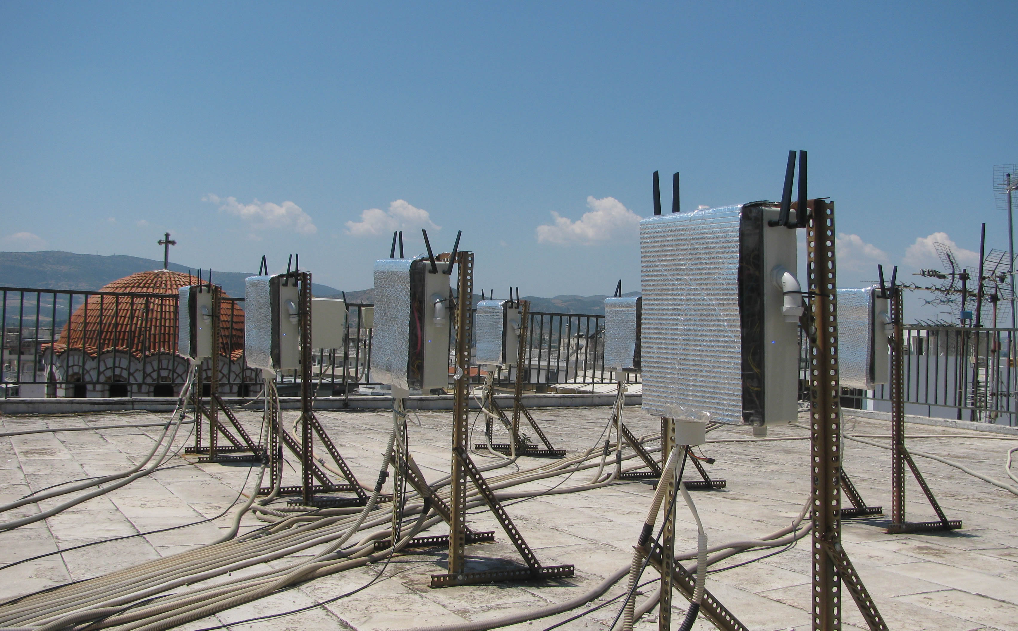
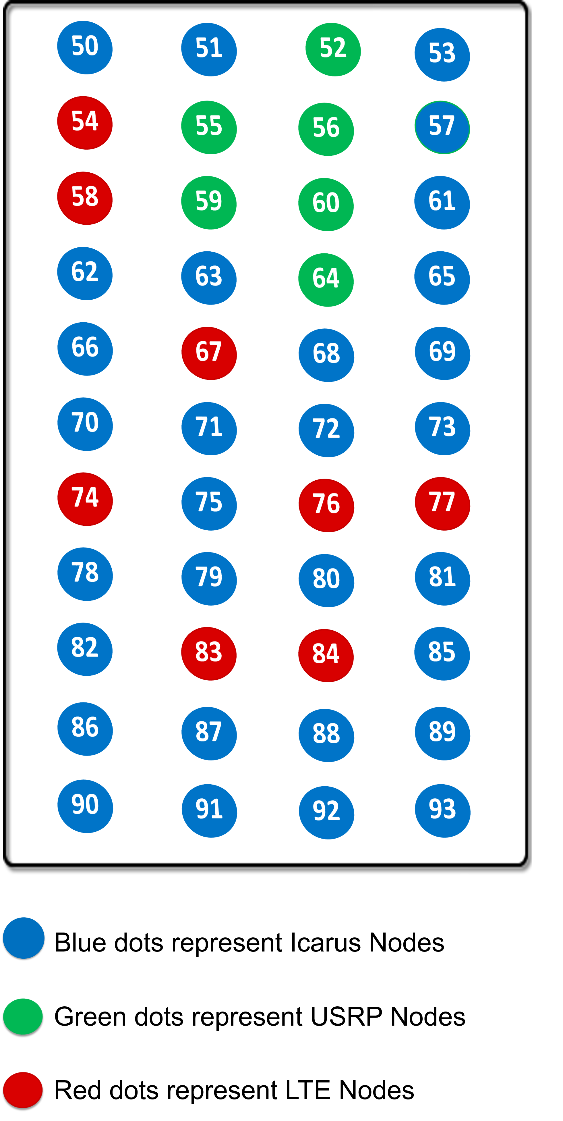
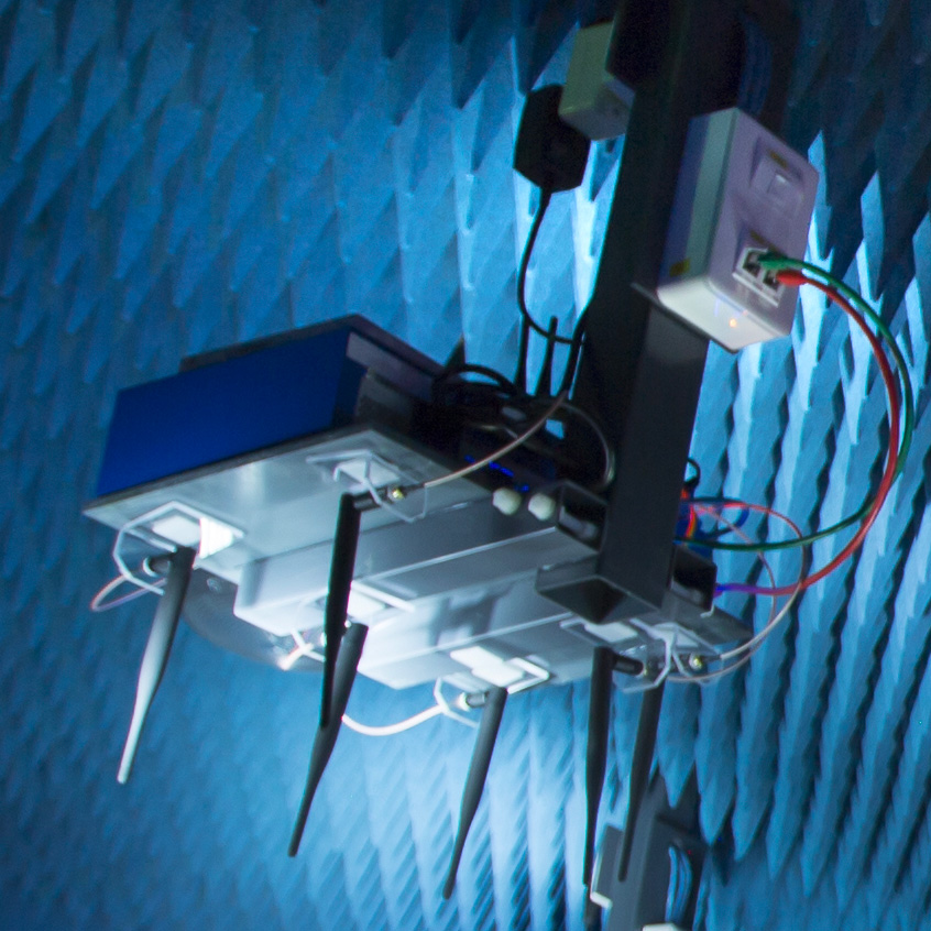
The NITOS RF Isolated Indoor Deployment consists of 50 Icarus nodes that feature multiple wireless interfaces (Wi-Fi, WiMAX, LTE) and is deployed in an isolated environment at a University of Thessaly's campus building. Experimenters are able to run and evaluate power demanding processing algorithms and protocols in a large scale testbed. It is also equipped with directional antennas and other advanced prototypes.
| Orbit nodes | 50 |
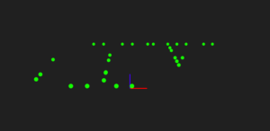
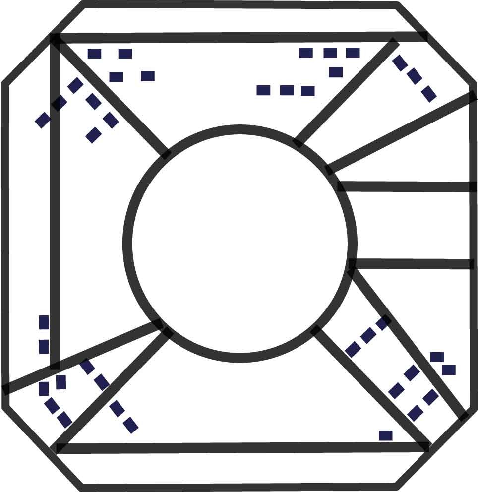
The Icarus nodes are placed in a symmetrical way around the isolated environment of NITOS indoor testbed forming a grid topology. The distance amongst the nodes is fixed to 1.2 meters and the height level is identical for all them as well. As a result, a uniform environment is created where all nodes are isobaric and of equal capabilities. You can find below a picture of the topology of the NITOS indoor testbed.
Nodes are deployed at the basement of a University of Thessaly (UTH) campus building.
| WSN430 open nodes | 256 |
| fixed | 224 |
| mobile on trains | 32 |
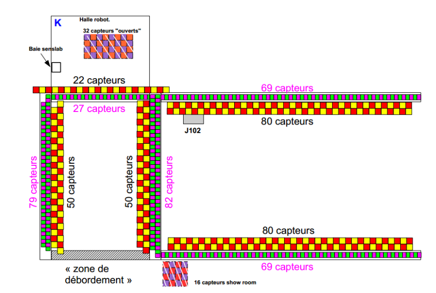
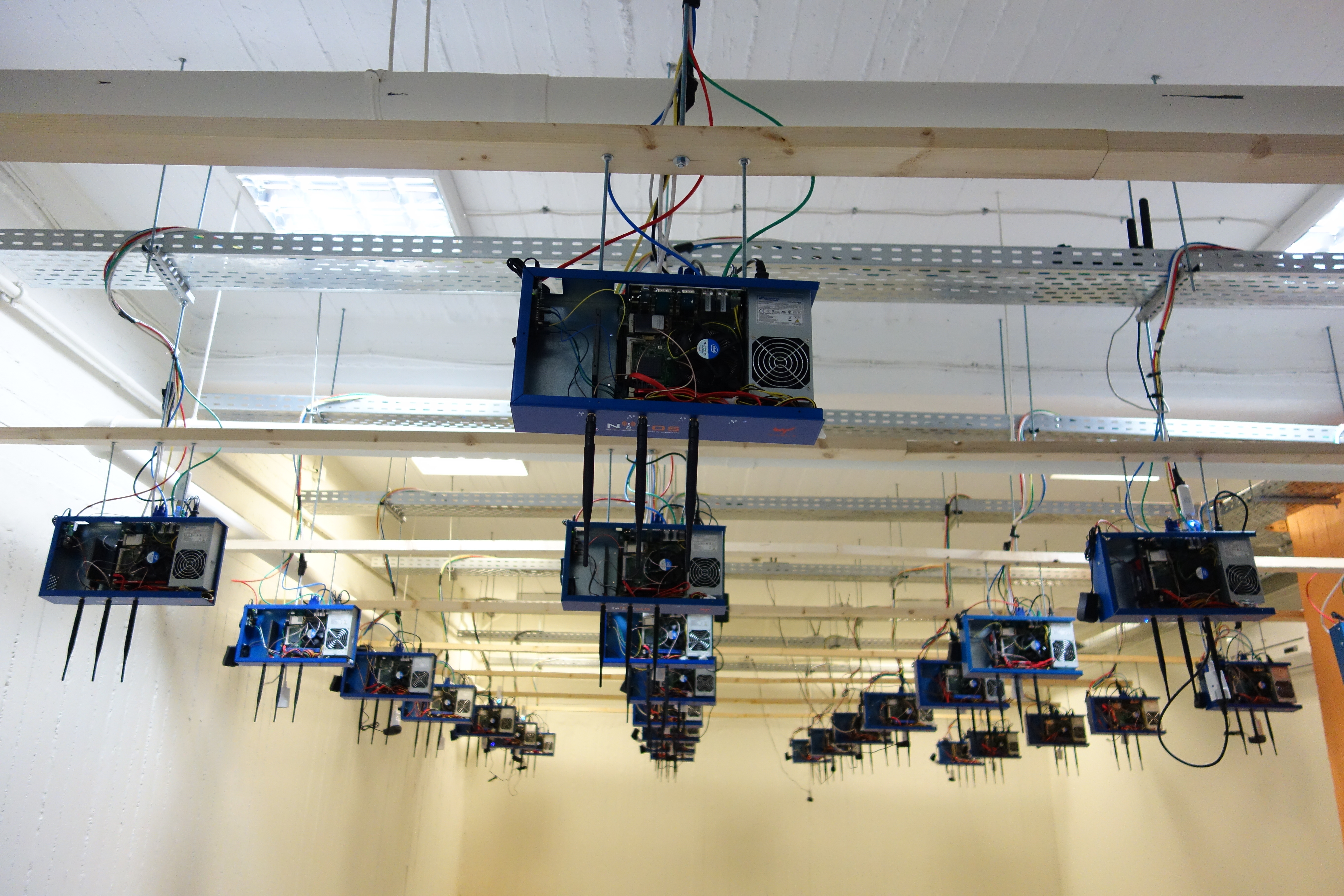
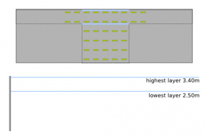
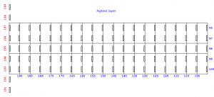
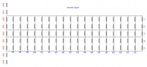
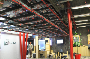
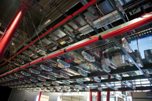
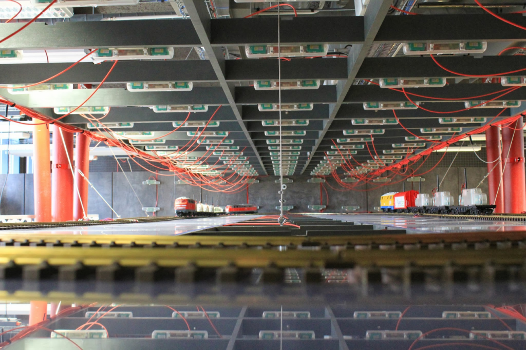
LEuratechnologies testbed is deployed in the Inria Lille – Nord Europe showroom.
Our nodes are deployed on: two horizontal layers (grid of 5 x 19 nodes) attached to a wall (containing 34 nodes); at a distance of 0.60 m to each others.
The lowest layer receives electric toy trains on two circuits, bringing mobile nodes for experiments.
Detailed testbed documentation one can find on GitHub Pages
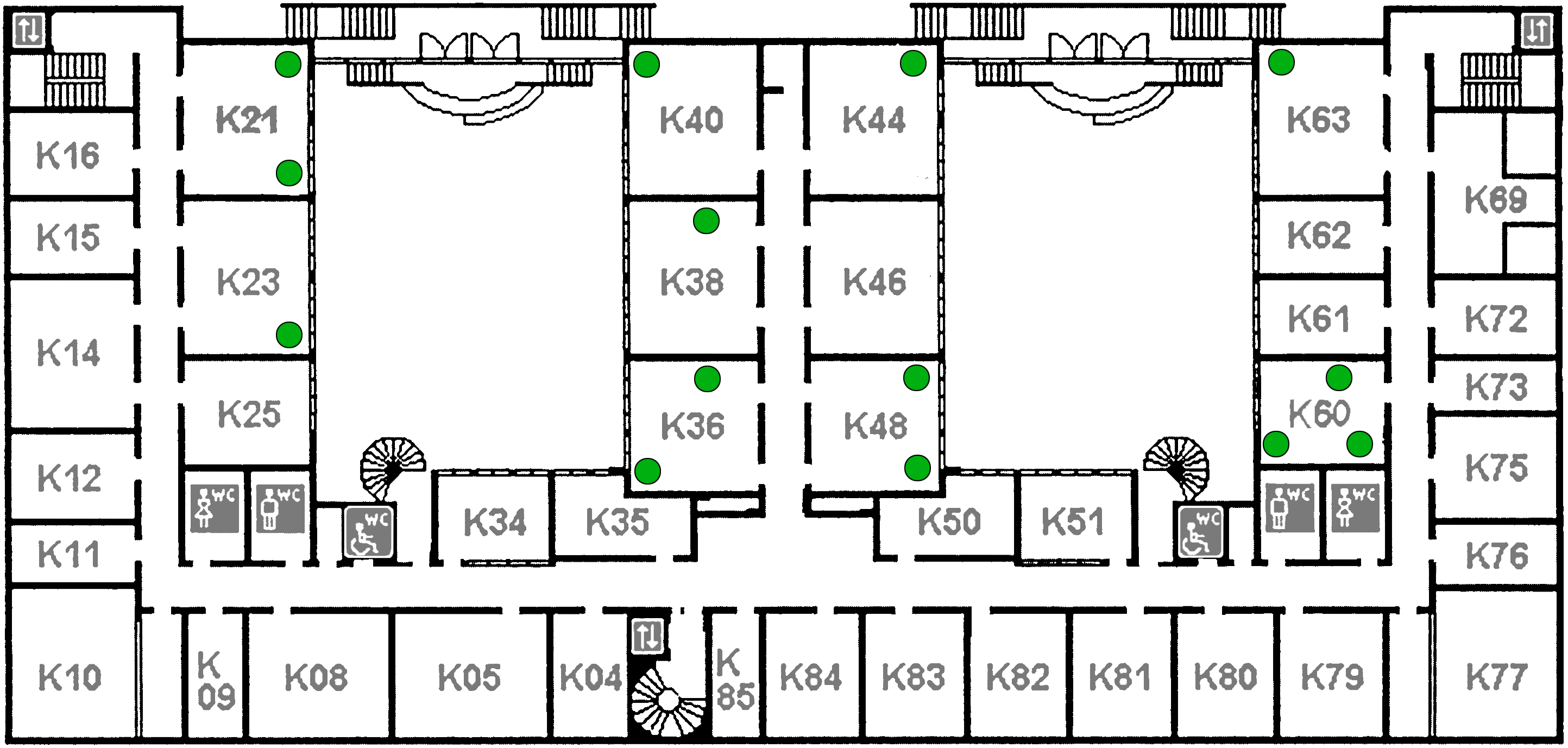
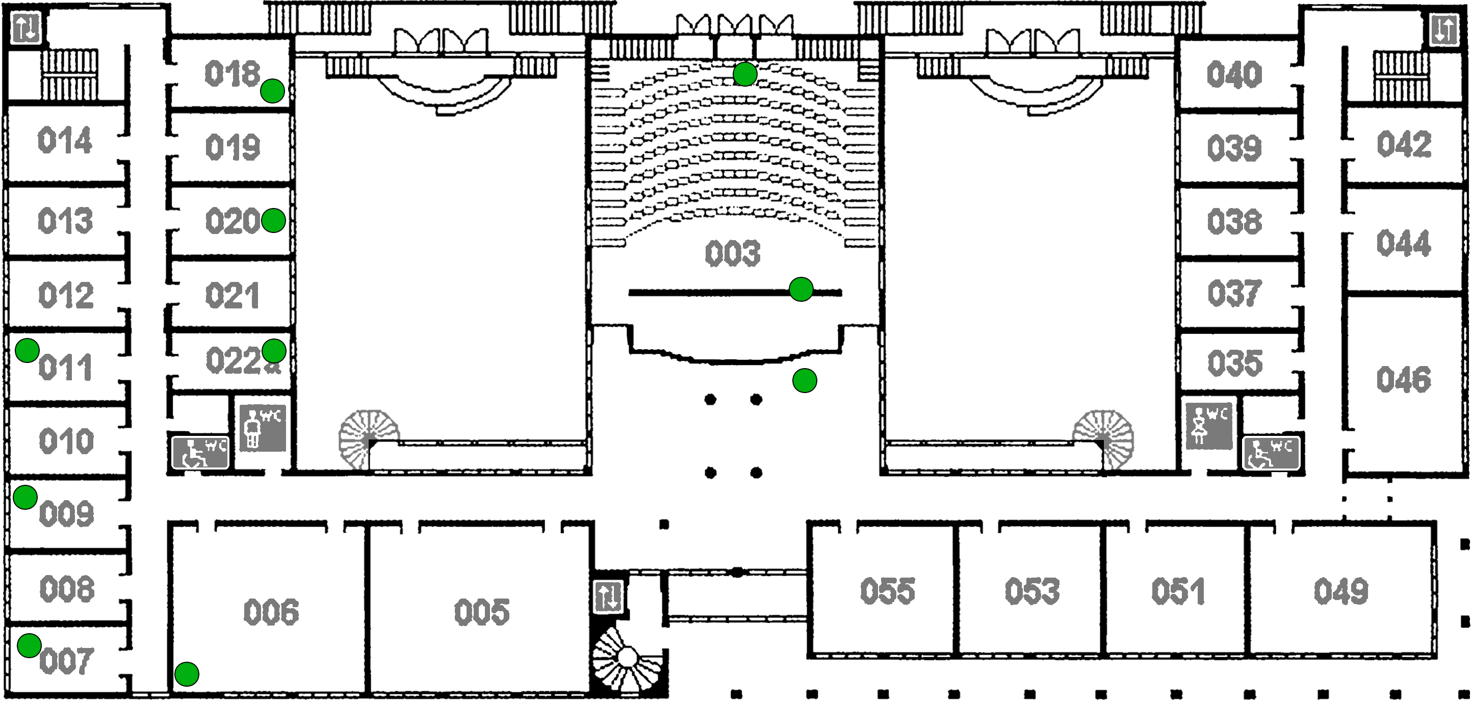
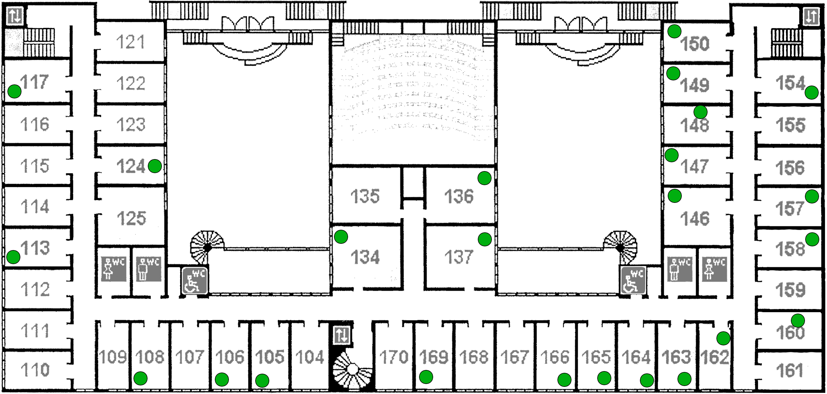
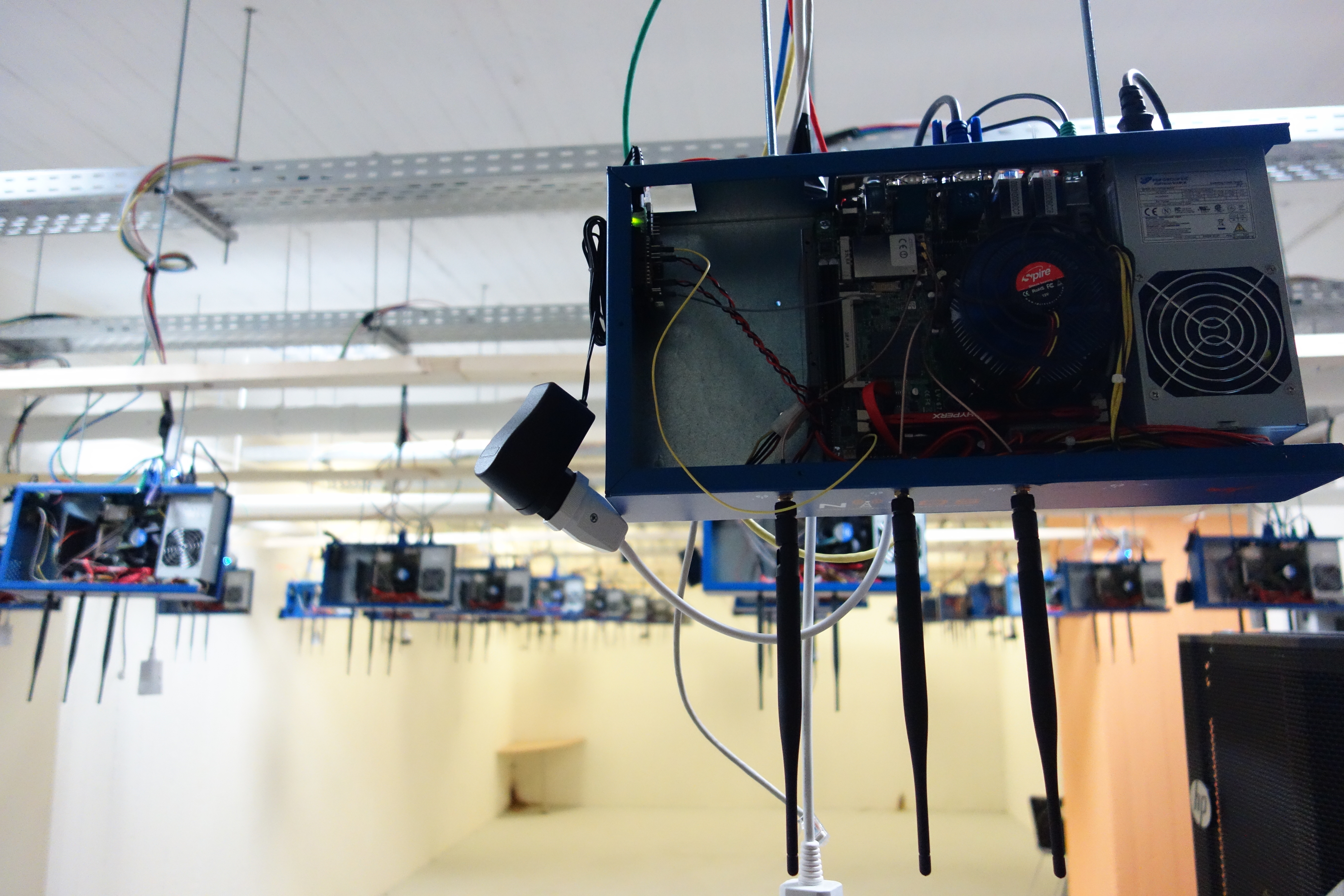
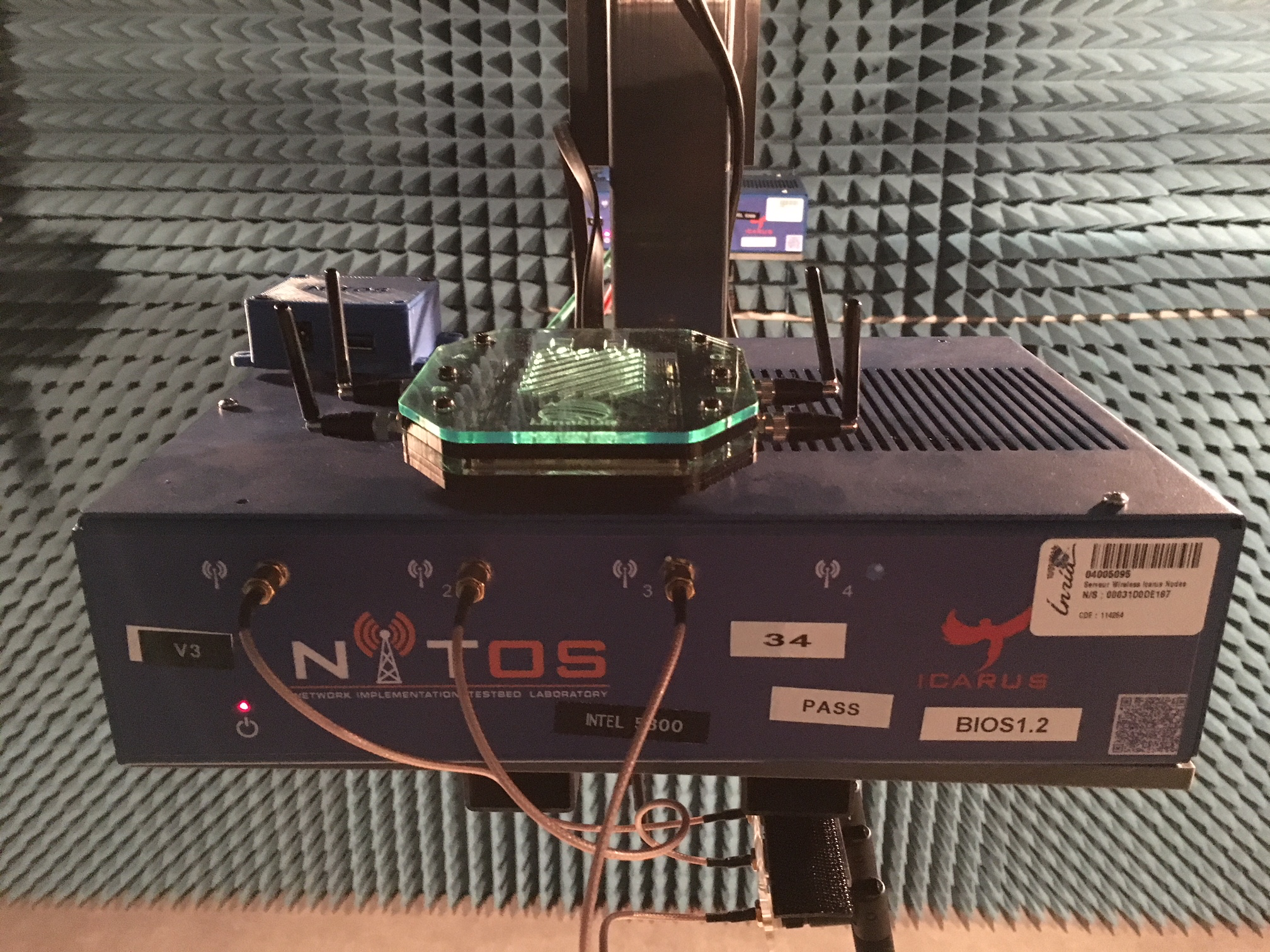
The FIT Wireless Paris platform is located at the LIP6 laboratory of the Sorbonne Université (SU) in Paris. The FIT Wireless Paris platform has 40 wireless Icarus nodes that are designed to achieve reproducibility of experimentation and testing in real world settings. The FIT Wireless Paris platform joins the NITOS Volos platform in providing nodes based on Linux open sourced drivers and wifi cards, with OMF open-source software as a control and management system.
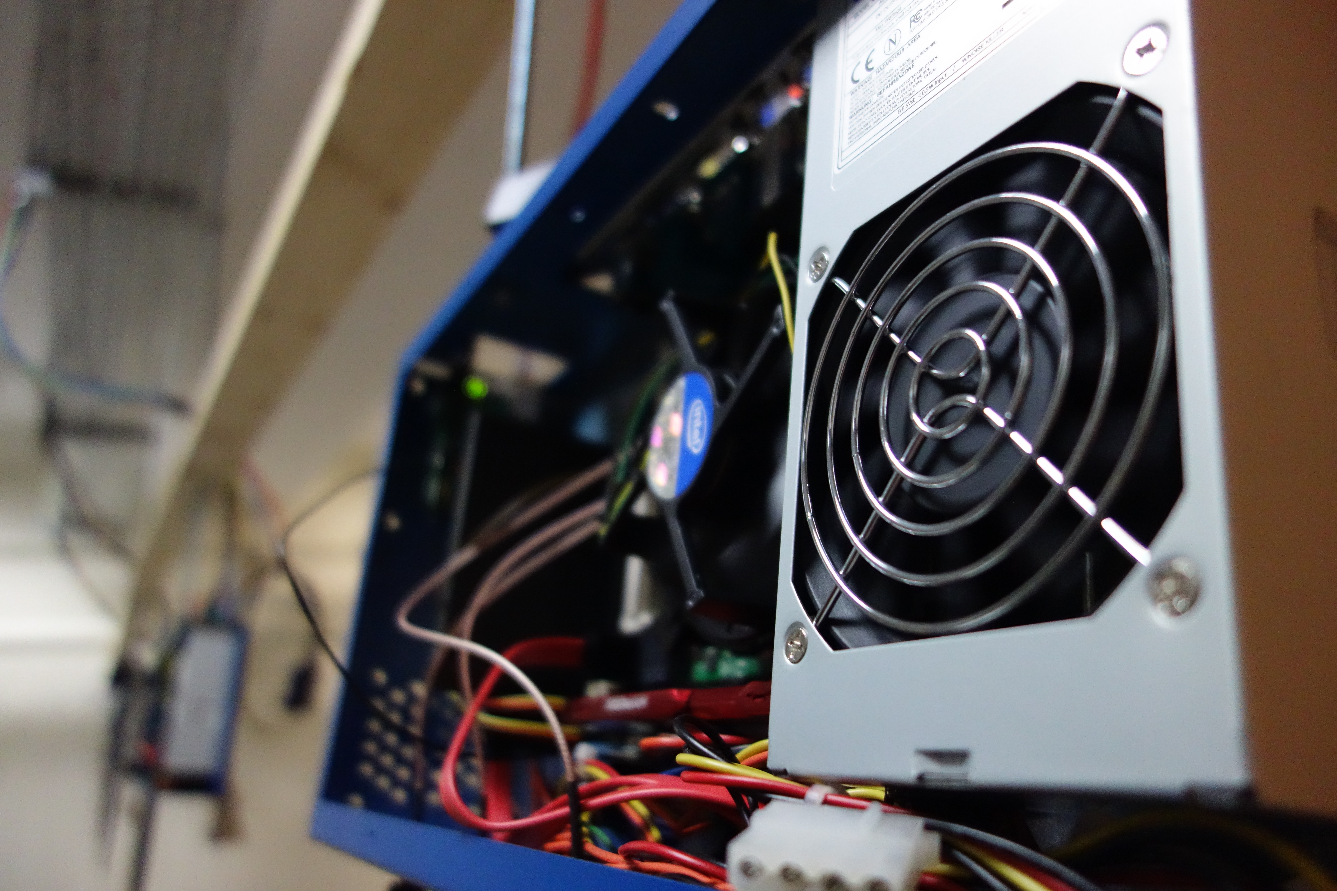
FIT Wireless Paris testbed is comprised of 40 Icarus nodes that are installed in the ceiling of the LIP6 laboratory rotunda. These nodes were developed by NITLab at the University of Thessaly and also make up up the NITOS Volos testbed. Icarus nodes are equipped with 802.11a/b/g and 802.11a/b/g/n wireless interfaces and feature new generation intel 4-core cpu's and new generation solid state drives.
NITlab's Chassis Manager Card (CM card) is used to control and monitor the operation of the FIT Wireless Paris testbed. A tiny web server is running on the CM card, and serves http requests such as power on/off and reset commands. The CM card can also support real time sensor measures, as it can be connected with temperature & humidity sensor as well as with light sensors.
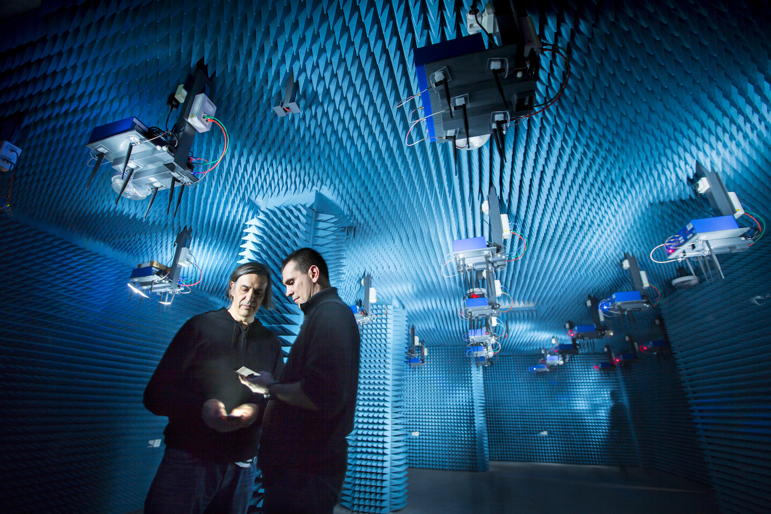
R2lab is an open tested located in an anechoic chamber for reproducible research in wireless WiFi and 4G/5G networks.
R2lab is part of the FIT federation, an open large-scale testing infrastructure for systems and applications on wireless and sensor communications.
Located at INRIA Sophia-Antipolis, R2lab proposes thirty seven customisable commercial off-the-shelf wireless devices, together with USRP nodes and commercial LTE phones, fit to create rich experimental setups. The testbed also features advanced software like leverage GnuRadio and OpenAirterface, as well as efficient software tools, to support easy experimentation.
These tools allow to book the whole testbed, to remotely control the wireless devices, to easily deploy various scenarios and to collect results.
Click one of these maps to see a virtual tour centered at the corresponding red crosshair. This opens in a separate window or tab; you will need to accept the SSL certificate from on.bubb.li that hosts the panoramic pictures. Just close the window to come back here.
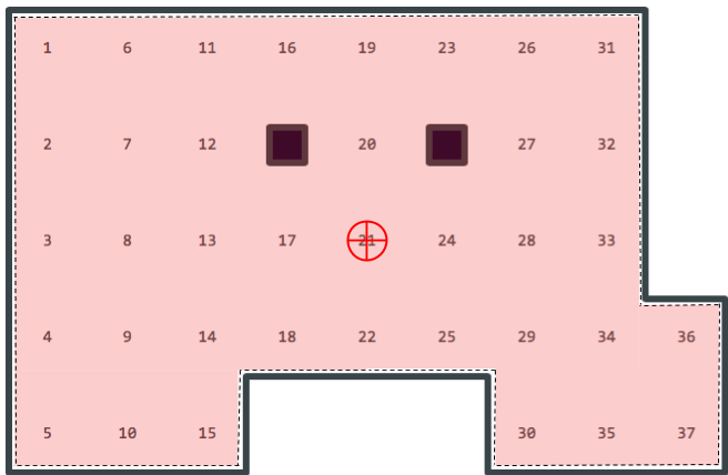
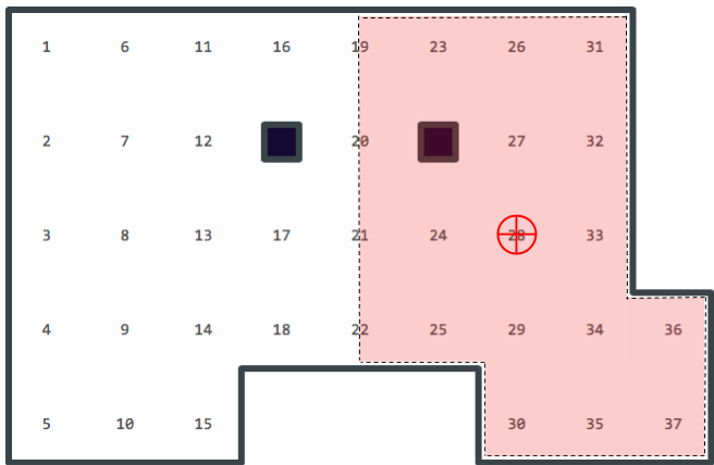
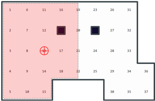
The R2lab platform sits in an insulated anechoic chamber of ≈ 90m2. It hosts thirty-seven nodes scattered on a fixed grid; about one third of these nodes feature a USRP board, of various kinds. In addition, commercial phones are available for connecting to a simulated 4G network.
All these resources can be controlled remotely through a unique ssh gateway at faraday.inria.fr. Users have full control, and can run their OS of choice with any experimental software they need for achieving their goals.
Experiments can thus be orchestrated with standard tools. For convenience, we also provide software tools as python libraries (see more details and tutorials here), that allow to quickly script efficient experiment deployment capabilities, complete from nodes provisioning to data collection. Check out our YouTube videos for more information.
Also you can load your operating system of choice on any node. From that point you can ssh-access all nodes with administration privileges, and configure the available resources - nodes, SDRs and phones - to create a rich experimental environment.
The testbed is reservable as a whole. Once they have booked the testbed, registered users can ssh into faraday.inria.fr, and from there control all the resources in the testbed. You are thus in full control of all the radio traffic in the chamber.
Some nodes are equipped with USRP devices from ETTUS to run SDR-based experiments such as spectrum analyzer or 4G/5G OpenAirInterface scenarios. All these devices can be remotely-controlled through the ust/uon/uoff utilities.
Currently, our deployment features the following types of USRP devices:
Here are the detailed specifications for the LimeSDR devices deployed in the chamber (see table below for the details on which nodes host such devices)
the following table shows in the usrp columns the type of the attached SDR, if present
the n210 and usrp2 models use an Ethernet connection to link to the node. This means that on those nodes, the data wired interface is not available, as the hardware interface is wired into the USRP device.
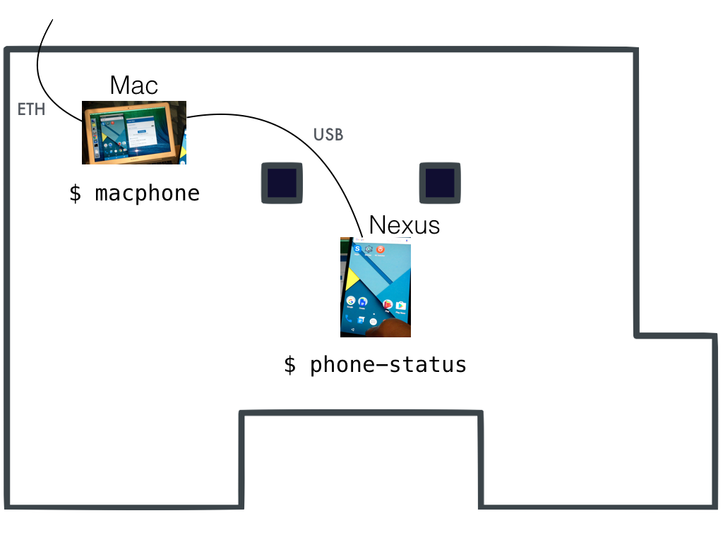
It is reachable through a Mac (that also sits in the room) that has its wireless card physically disabled, and that has a USB cable to the phone
The Mac can be reached from the gateway as ssh tester@macphone (or the macphone convenience shell shortcut)
Once logged in the Mac you can use convenience helpers to manage the phone (type help for details), or use adb manually.
The mac can also be managed using apple screen sharing tools (VNC-compliant), pointing directly at faraday.inria.fr
You will find more details about controlling the phone in the tutorials section.
Some USRP devices, like the b210, have their Tx and Rx SMA connectors very close to one another. For that reason some have a device named a duplexer band 7 [specs][pict].
The settings used in our deployed duplexers match the frequencies used in our default configuration for OpenAirInterface. That is to say, it is assumed that
In the duplexer column below, devices are tagged as either none, for UE or for eNB.
source: https://r2lab.inria.fr
 - Paris
Cloudlab is a research platform for building clouds. It provides researchers with access to the bare metal, and control over computing, storage and networking resources. Users can deploy new, existing or modified cloud software stacks within minutes and test them using this platform. The platform also provides hard isolation of the resources from other users and supports over hundred simulatanous experiments.
With the collaboration of Cloudlab and Onelab, Onelab users can now use their Onelab credentials to reserve and use Cloudlab's resources
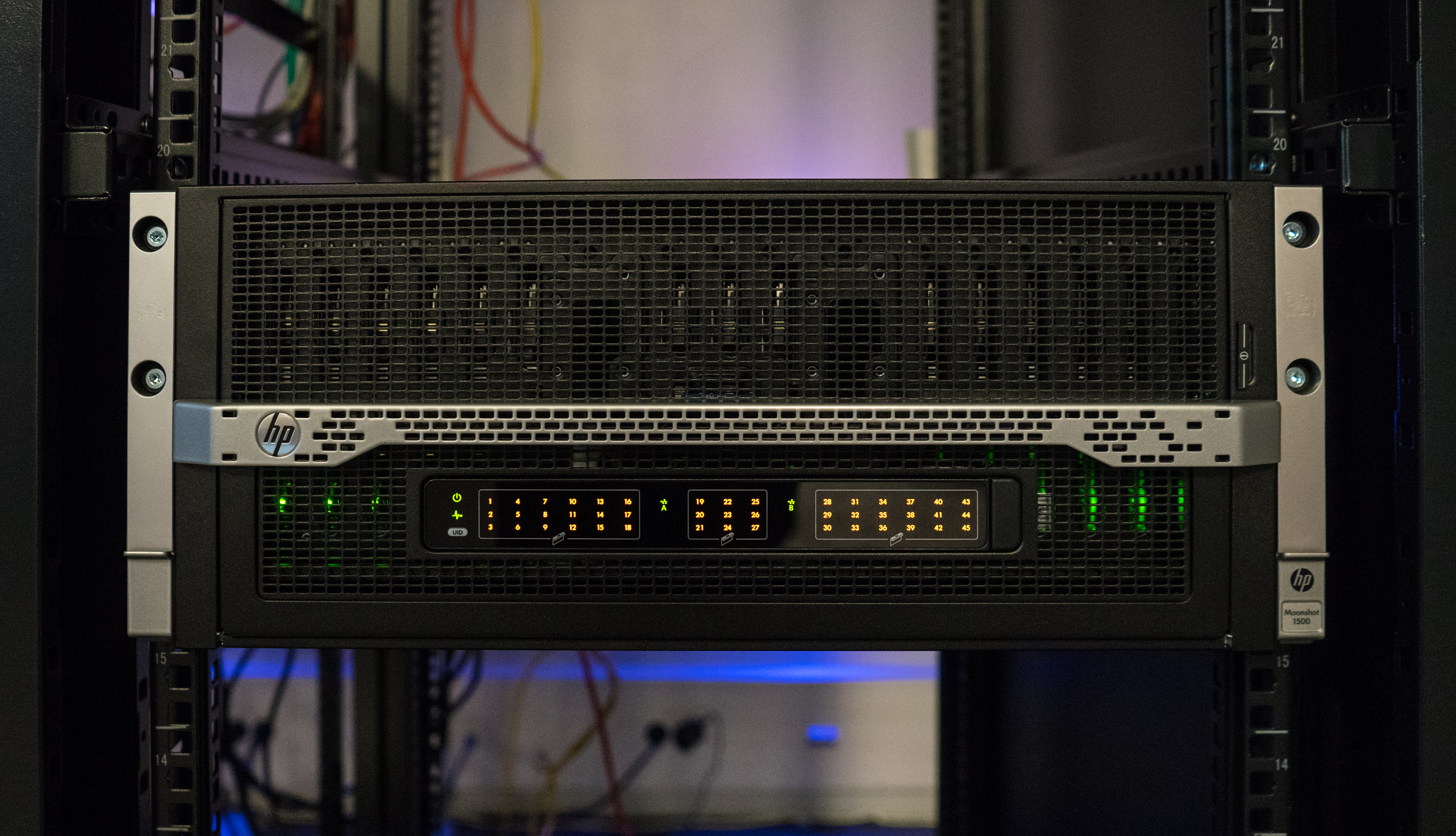
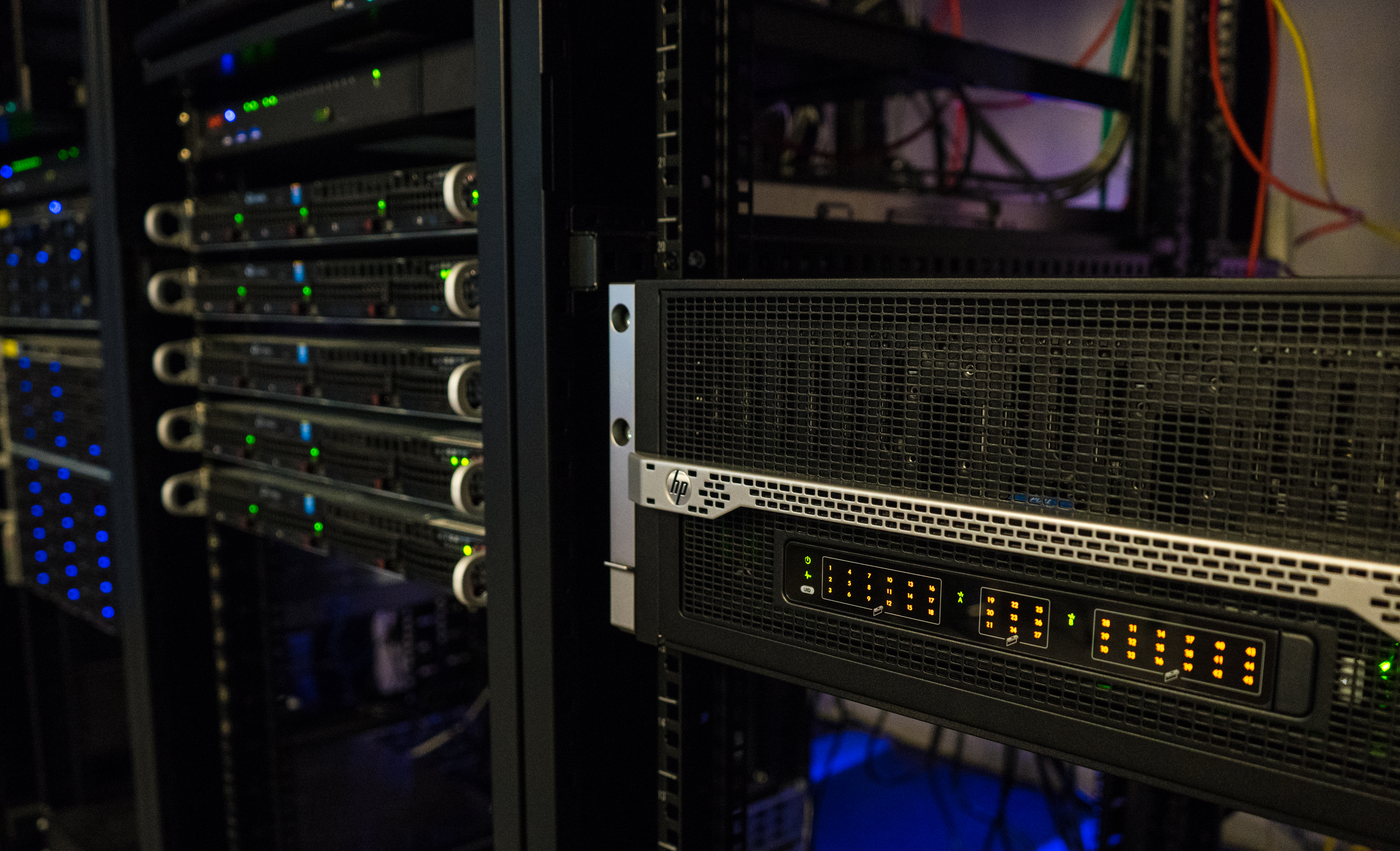
Cloudlab offers over 15 000 computing cores over different sites. And here in the infrastructure of Onelab at Paris, we have deployed 45 m400 nodes.
| m400 nodes | 45 |
Other types of hardware from different sites of Cloudlab are also available. For the full list of available hardware, click here
Tutorial : Sign in to Cloudlab using your Onelab credentials
Documentation : Cloudlab platform documentation
 - Paris
FIT Cloud or FIT Openstack Cloud is a research platform that provides researchers with access to customizable virtual private servers on the Openstack Cloud. Users can customize their virtual servers with the CPU, Memory and Storage of their choice through the portal. The virtual servers will be available within minutes. The platform provides over a hundred of computing cores and 1TB of RAM (...) are made available
FIT Cloud offers over a hundred of computing cores. The current cluster is composed of 3 controllers nodes and 4 computes nodes
| Model | DELL PowerEdge R740 | |
| CPU | 16 cores Intel(R) Xeon(R) Silver 4110 CPU | |
| RAM | 32GB ECC Memory | |
| NIC | 2x 10GB SFP+ + 2x Ethernet |
| Model | Supermicro X9DRW |
| CPU | 32 cores Intel(R) Xeon(R) CPU E5-2650 0 |
| RAM | 256GB ECC Memory |
| Disk | 4TB HDD |
| NIC | 2x 10GB SFP+ + 2x Ethernet |
| Model | DELL PowerEdge R640 |
| CPU | 64 cores @ 2.9 Ghz Intel(R) Xeon(R) Gold 6226R CPU |
| RAM | 256GB ECC Memory |
| Disk | 4TB HDD |
| NIC | 2x 10GB SFP+ + 2x Ethernet |
Tutorial : How to reserve a cloud resource
Documentation : How to automatize configuration scripts
![[pict]](https://r2lab.inria.fr/raw/docs/duplexer-band7.png)